Set Up Flowsheets
In Wood InsightsPlatform (WIP), you can create, update or delete flowsheets using the Flowsheet Manager as described below. For information about the layout and usage of the Flowsheet Manager’s user interface, see Flowsheet Manager.
Create Flowsheets
Choose from the main menu.
In the Flowsheets pane, click Configuration on the toolbar to enter editing mode.
Click New on the toolbar.
In the New Flowsheet dialog, enter data as follows:
Name: Enter a name that uniquely identifies the flowsheet.
Display Refresh Interval (seconds): Specify how often the flowsheet display should update when in Viewer Mode (in seconds).
Description (optional): Add a brief description to explain the purpose or contents of the flowsheet.
Save your entries.
Drag elements from the Palette onto the designer area. You can add the following types of elements:
IO element (under Basic): Input or output elements that are used to either input a tag value into a flowsheet or output a value from a function block back to a tag. Represented by a circular element in the flowsheet.
Function Block element (under Basic): Empty function block elements that allow you to specify your calculation logic as scripts or code. Represented by a square element in the flowsheet.
Function Block Template element (under specific categories): Function blocks with preconfigured logic (see Configure Function Block Templates). If categorised, they are listed under their assigned categories; otherwise, they appear under the Unassigned category.
Note
To delete an element, select it and press Delete / Backspace on your keyboard.
To move an element around, first click to select it, then drag it to the desired location.
Configure individual elements in the flowsheet:
IO element: Double-click the IO element to open the configuration dialog. Enter a name and, optionally, a description. You assign tags to IO elements when you create the flowsheet instances and mappings (see Set Up Flowsheet Instances and Mappings).
Function Block element: First, click the function block to select it (this will show the main parameters of the function block in a pop-up pane), then double-click the function block to define its parameters. In case of new function block elements, you must configure the function block parameters and assign the pins. For more information, see Configure Function Blocks.
Function Block Template element: First, click the element to select it (this will show the main parameters of the function block in a pop-up pane), then double-click to edit its name and description. To update other parameters, you must update the function block template itself (see Update Function Block Templates).
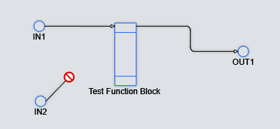
Connect the elements of the flowsheet.
Each element has connection points that allow you to connect the element to another. Press a connection point and drag it to connection point of another element to form a connection. While dragging the connection, a red icon is shown until you reach a valid connection point:
The number of connection points depend on the type of the element:
IO elements have two connection points, one for input, another for output and they are shown by a + sign when hovering over the element:

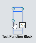
Function block and function block templates have as many connection points as many pins have been added to the element when configuring them. Connection points are shown by a o sign when hovering over the element. For example, if you have added two input and one output pins to the function block, it will have three connection points:
Note
To delete a connection, select it and press Delete / Backspace on your keyboard.
Set up flowsheet instances and map a tag to each IO element on the Instances & Mappings tab. You must set up at least one flowsheet instance. For more information, see Set Up Flowsheet Instances and Mappings.
Configure Function Blocks
Once you have added a new function block to a flowsheet (see above), you must set up its input and output pins and define its core code or logic. For more information about function blocks, see Function Blocks.
Click the new function block in the flowsheet, then double-click it to open the Function Block dialog.
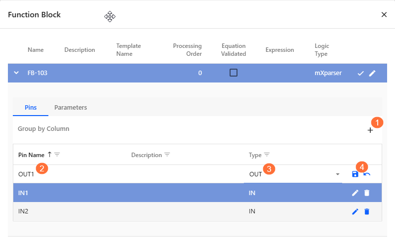
On the Pins tab of the dialog, add input and output pins as follows:
At the top right side of the tab, click
 .
. 
In the new row that is added, make the following entries:
Pin Name: Specify the name of the pin (alphanumeric only, no special characters). This name will represent the pin in the expression of the function block.

Description: Enter a description if required (optional).
Type field: Select IN or OUT to determine if the pin is an input or an output for the function block.

Click
 to save the new entry.
Repeat the steps above until all the pins have been added.
Optionally, you can define parameters to use within the expression of a function block. A parameter is a named variable with a constant value, such as a fixed number or unit. To create a parameter:
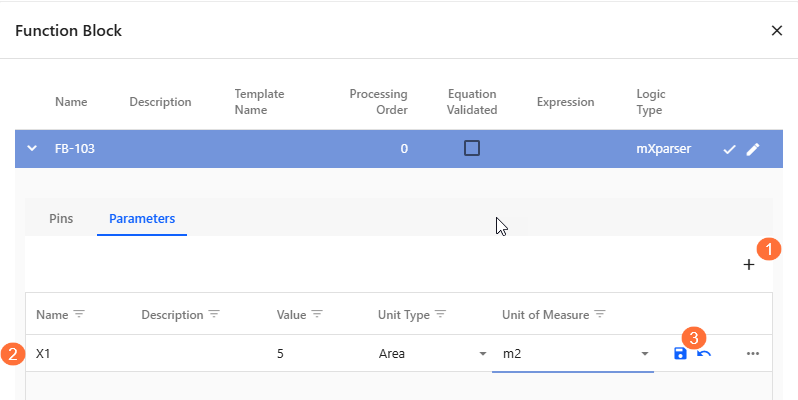
Go to the Parameters tab of the Function Block dialog.
At the top right side of the tab, click
. In the new row, make the following entries
:Name field: Enter a unique name for the parameter
Description: (Optional) Add a brief description of the parameter.
Value: Enter the constant value for the parameter.
Unit Type: Select the appropriate unit type (for example, Area, Distance).
Unit of Measure: Choose the unit (for example, m², m, kg).
Read Only: Select this option if the parameter should not be modified during execution.
Click
to save the new entry .
Once defined, you can reference the parameter by name in the expression field of the function block. For example, if you define X1 as an area with a value of 5 m², you can use X1 in your logic, and it will be replaced with the defined value during calculation.
Define the main parameters and logic of the function block.
In the Function Block dialog, click the
 icon on the right side of the function block details.
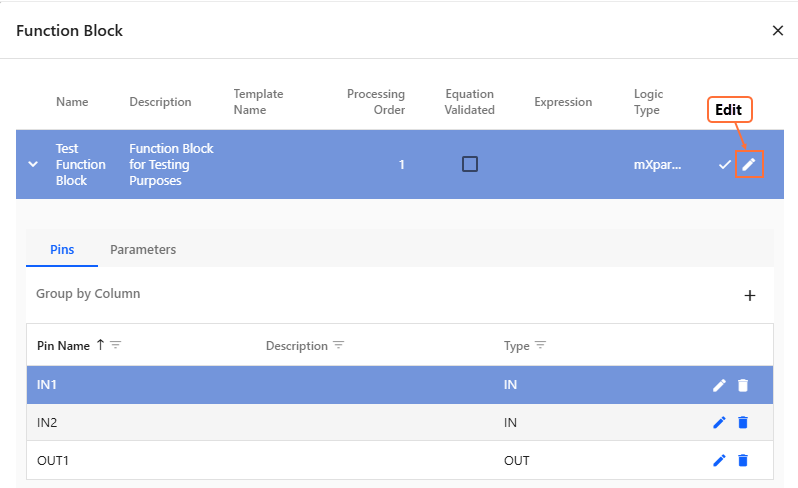
In the FB Configuration dialog, enter data as follows:
Field
Description
Name
Enter a name that uniquely identifies the function block.
Description
Provide additional information about the function block’s purpose.
Processing Order
Enter a numeric value to define the sequence in which this function block is evaluated relative to others. Lower numbers are processed first. Use this to control execution flow when multiple function blocks are used in the same flowsheet.
Logic Type
Select the logic engine that interprets the logic in the Expression field:
mXparser: for mathematical expressions using mXparser syntax.
Python: for logic written in Python.
Thermo: for thermodynamic-specific logic (if applicable).
For more information about these logic engines, see Calculation Logics.
Secure Equations
This feature is used to lock the expression and prevent unauthorised editing or viewing. Secure Equations could be delivered as part of a project in order to protect sensitive or proprietary logic. Note that a password will be required to view/edit the equation once secured. The default password is known only to Wood and may optionally be adjusted during project setup.
Expression
Enter the logic for the function block using one or more equations. Each equation must be placed on a separate line.
If using mXparser logic, note the following:
Each equation must end with a semicolon (;).
You can include comment lines by prefixing them with //.
Any argument that matches a pin name or parameter name will use the corresponding pin I/O mapped value or parameter value.
Arguments that match a pin name with the suffix xQV will access or assign the quality of that pin.
Arguments that do not match any pin or parameter name will be treated as internal variables within the expression.
For example, if using mXparser and you have defined input pins IN1, IN2, output pin OUT1, and a parameter X1, the expression can be:
OUT1 = IN1 + IN2 + X1;For more information, see mXparser Calculation Logic.
Validate Equations
Click this button to check the syntax and logic of the expression based on the selected Logic Type.
If the expression is valid, a green message confirms successful validation.
If there are errors, a red message appears with details to help correct the issue.
Equation Validated
A system-controlled checkbox that is automatically checked when the expression passes validation. This provides a quick visual indicator of whether the logic has been successfully verified.
Save your entries.
Set Up Flowsheet Instances and Mappings
The calculation service supports flowsheet instancing, a feature designed to simplify the reuse of flowsheets that perform similar calculations. This is particularly useful when the same logic needs to be applied multiple times, as it avoids duplicating entire flowsheets. This is an approach that can increase maintenance overhead and complexity. Instead, users can create multiple instances from a single flowsheet, promoting consistency and efficiency.
Once a flowsheet instance is created, it must be configured with the appropriate IO mappings. These mappings are the primary distinction between instances, as they define how each one connects to external data sources. Specifically, IO mappings associate the flowsheet’s input and output points with the relevant WIP tags. Each IO must be correctly mapped to ensure accurate data flow and proper instance behavior.
This section provides detailed steps for creating flowsheet instances and configuring their IO mappings.
Choose from the menu.
On the Flowsheets pane, click Configuration on the toolbar to switch to editing mode.
On the left side of the pane, select the flowsheet for which you want to create a new instance from the list under Flowsheets.
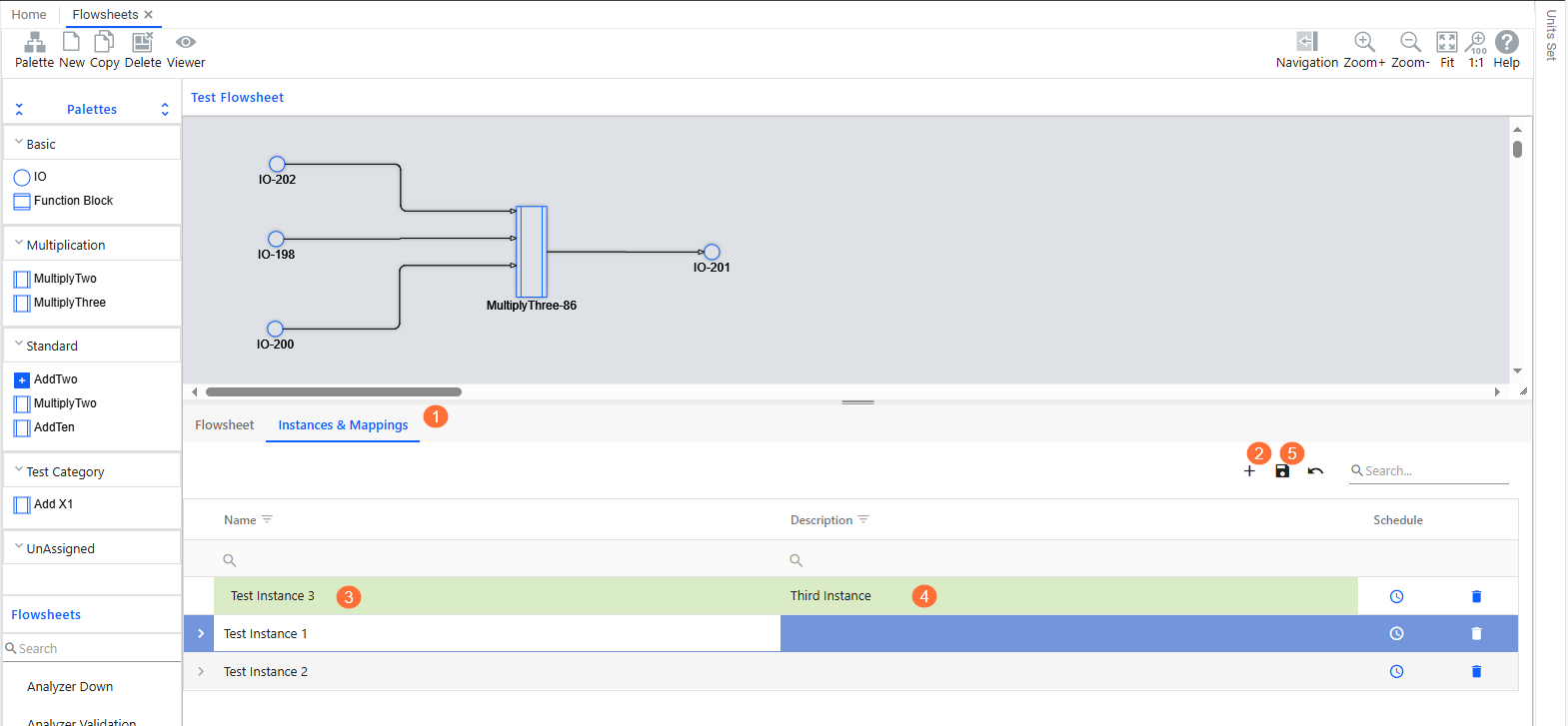
Create a new flowsheet instance.
Go to the Instances & Mappings tab.
At the top right side of the tab, click
. In the new row, make the following entries:
Name: Specify the name of the instance.
Description: Enter a description if required (optional).
Click
 at the top of the tab.
Result
The system automatically adds a new IO mapping row for each IO element in the flowsheet.
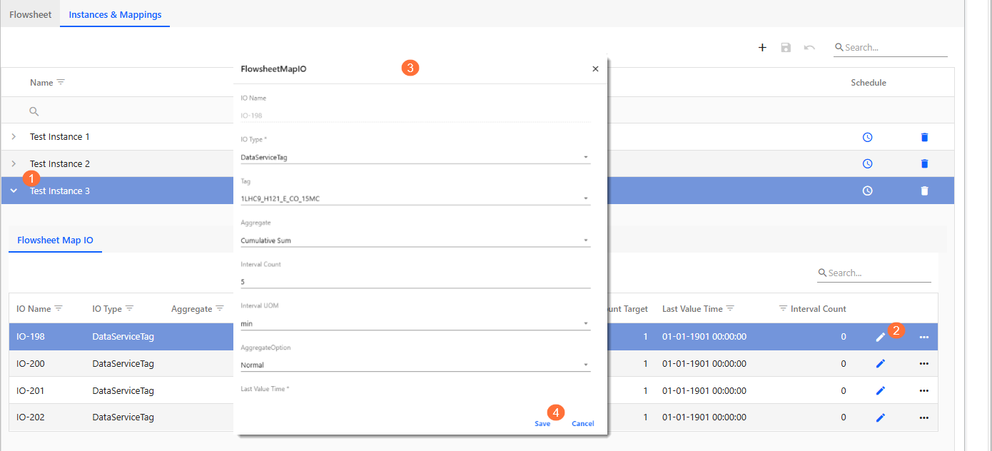
Set up IO mappings.
On the Instances & Mappings tab, expand the details of the new instance by clicking
 at the start of the row.
 For each IO row (added automatically by the system for IO elements), click
 to configure their mappings.
 In the FlowsheetMapIO dialog, enter data as follows:
Field
Description
IO Type
Select one of the following options to define the source or nature of the IO element:
DataServiceTag: The IO element is linked to a tag and retrieves or outputs values through it. The fields described in this table are applicable when this option is selected.
ElementProperty: The IO element is associated with a property of an asset. You must select the asset, its property, and the relevant unit type and unit of measure.
Constant: The IO element holds a fixed value. You must specify the constant value along with its unit type and unit of measure.
Tag
Select the relevant tag from the dropdown list.
Aggregate
Represents the type of aggregation to apply to the IO point. This field is used for inputs to a function block. Outputs from a FunctionBlock are always stored as the Raw value.
Available options include:
Raw: The unprocessed, base value of the tag.Mean{Interval}: Average value over the interval.Max{Interval}: Maximum value during the interval.Min{Interval}: Minimum value during the interval.Sum{Interval}: Total sum over the interval.CumulativeSum{Interval}: Last cumulative sum value.First{Interval}: First value in the interval.Last{Interval}: Last value in the interval.
Period-Based Aggregates (timestamped at start or end of interval):
Mean (Period){Interval}: Returns the average for the last full period, or the last partial period if a full one is not available. Example: For a 1-hour interval, returns the average from the previous hour.Sum (Period){Interval}: Returns the total for the last full or partial period. Example: A 1-hour interval returns the total from the previous hour.Min (Period){Interval}: Returns the minimum value for the previous period, timestamped for the period, not the actual time of the minimum.Max (Period){Interval}: Returns the maximum value for the previous period, timestamped for the period.First (Period){Interval}: Returns the first value for the previous period, timestamped for the period.Last (Period){Interval}: Returns the last value for the previous period, timestamped for the period.
Moving Aggregates:
Moving Average (By Points){Interval, Frequency}: Computes a rolling average over the interval using the last N data points. Example: A 24-hour interval with 10-point frequency returns the 24-hour average from the last of the previous 10 points.Moving Average (By Time){Interval, Frequency}: Computes a rolling average over the interval using a moving time window. Example: A 24-hour interval with a 1-hour frequency returns the 24-hour average from the previous hour.Moving Total (By Time){Interval, Frequency}: Computes a rolling total over the interval using a moving time window. Example: A 24-hour interval with a 1-hour frequency returns the 24-hour total from the previous hour.
Rate and Accumulation Aggregates:
Derivative{Interval}: Calculates the rate of change (slope) over the interval.Derivative (Period){Interval}: Calculates the rate of change over the last full or partial period. Example: For a 1-hour interval, returns the rate of change from the previous hour.Integral{Interval}: Computes the accumulated value (area under the curve) over the interval.Integral (Period){Interval}: Computes the accumulated value over the last full or partial period. Example: For a 1-hour interval, returns the integral from the previous hour.
Interval Count
Specifies the numeric value of the interval used for aggregation. This works in combination with the Interval UOM to define the full time window (for example, 1, 5, 24).
Interval UOM
Defines the unit of measure for the interval count. Common units include seconds, minutes, hours, or days. Together with Interval Count, this determines the total aggregation window (for example, 1 hour, 24 hours).
AggregateOption
Specifies how data quality is handled when requesting aggregates from the Data Service. Only one option can be selected at a time (mutually exclusive).
Available options include:
Normal(default): All input points are used in the aggregate. The resulting quality reflects the worst quality among the inputs.AssumedGood: The quality is always set to Good, regardless of the actual input quality. (DataService: WithAssumedGoodQuality)OnlyGood: Only input points with Good quality are used. If no good points are available, the last good aggregate is used. If none exists, no value is returned. (DataService: WithOnlyGoodQualities)MinimumGood(bool) /Count Target(int): Requires a minimum number of good input points (defined by Count Target) for the aggregate to be considered valid. (DataService: WithMinimumNumberOfGoodQualitiesInWindow)WithoutQuality: Disables quality tracking entirely. (DataService: WithoutQuality)
TimestampLocation
Applicable to period-based aggregates. Specifies where the result is timestamped:
End of Interval(default): Timestamp at the end of the period.Start of Interval: Timestamp at the beginning of the period.
Example: A 1-hour
PeriodMaxvalue set toStart of Intervalwould return the maximum value for the period (as defined by the interval), but timestamped at the beginning of the period. The defaultEnd of Intervalwould timestamp the value at the end of the period.Last Value Time
Used for historical calculations. Defines the starting point for processing tag values.
Unit Type
Shows the unit type associated with the selected tag. This value is filled in automatically based on the tag that you selected.
Unit of Measure
Specify the unit of measure to be used in expression calculations. For IO Type of Tags, the tag value is first converted to the specified unit of measure before being used in the expression. After computation, the result is converted back to the tag’s default unit for historical storage. For IO Types such as Constants and Element Property, no unit conversion is applied; values are used exactly as entered or received.
Save your entries.
Repeat the steps above for each IO mapping row.
Update Flowsheets
To edit existing flowsheets, you must switch to Configuration Mode in the Flowsheet Manager in the Flowsheets pane. You can then update the following:
You can update the name and description of the flowsheet as well as the display refresh interval on the Flowsheet tab under the designer area.
You can change the architecture of the flowsheet, that is, add, remove or move around elements or connections in the designer area using the functions described in Create Flowsheets.
You can add, edit or delete flowsheet instances and mappings on the Instances & Mappings tab under the designer area. For more information, see Set Up Flowsheet Instances and Mappings.