Configure Schematic Data Maps
Schematic data maps are configurations used to conditionally colourise nodes or components within a schematic diagram. By assigning these data maps to specific schematic elements, you can visually represent the status of these elements in the schematics. For example, you can set a node to turn red if its tag value is below a certain threshold, indicating a potential issue, and green if the value is above the threshold, indicating normal operation.
Set Up Schematic Data Maps
To set up a schematic data map, follow the steps below:
Choose from the menu.
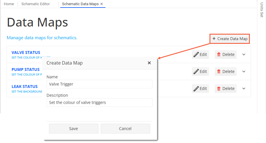
On the Schematic Data Map pane, click
 Create Data Map in the upper right corner of the pane.
Enter a name and a description and click Save.
Result
A new entry gets added to the pane with the name and description of the data map. If you want to edit the name or description of this entry or delete it later, choose
 Edit or
  Delete next to the entry, respectively.
Click the
 drop-down arrow at the right-hand side of the entry to expand its details.
To add the first condition, click
Add Entry and in the Create Data Map Entry dialog, enter values as follows:Field
Description
Name
Specify a name that uniquely identifies the data map entry.
Value
Enter the hex value of the colour you want to use.
Description
Specify the condition that triggers the colour change.
Save your entry.
Add further data map entries for conditions as required.
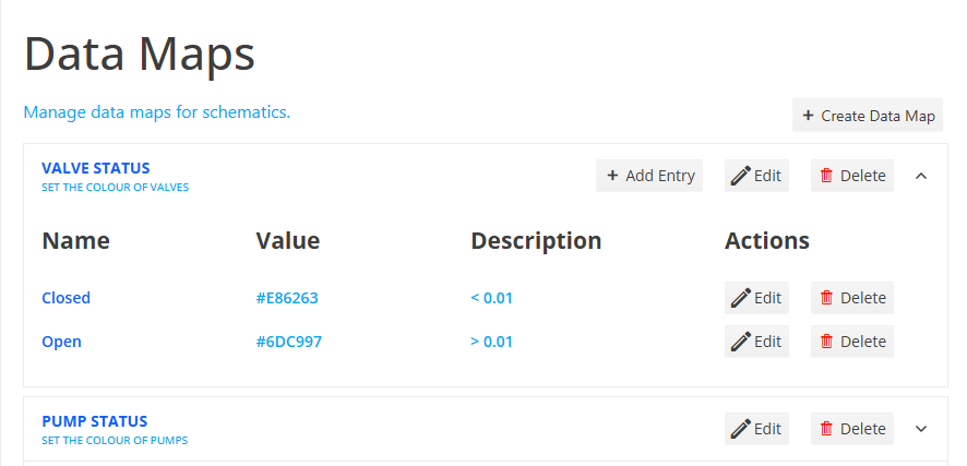
Example
The example below shows two data map entries, which set the colour of valve nodes based on the value of their assigned tag. When a node’s tag value is less than 0.01, it will return a colour value of #E86263 (red). If its tag’s value is greater than 0.01, it will return a colour value of #6DC997 (green).
Result
Changes to data maps are automatically saved and the colours are applied in the relevant schematics. You can update or delete existing entries using the
Edit or Delete buttons next to the relevant entries. Once you have set up the schematic data maps, you can assign them to the schematic elements (see Assign Schematic Data Maps to Schematic Elements).
Assign Schematic Data Maps to Schematic Elements
Once you have set up schematic data maps, you can assign them to specific schematic elements in the Schematic Editor (see Set Up Schematics). Various types of schematic elements allow you to assign a data map in their configuration options. To assign a data map to an element, follow these steps:
In the Schematic Editor, click on the element you want to configure.
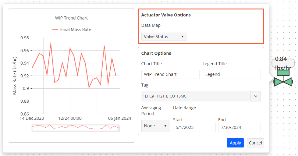
In the configuration dialog that appears, locate the Data Map field.
Select the appropriate data map from the dropdown menu.
See an example of data map assignment for a valve below:
See also